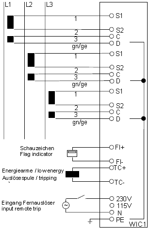
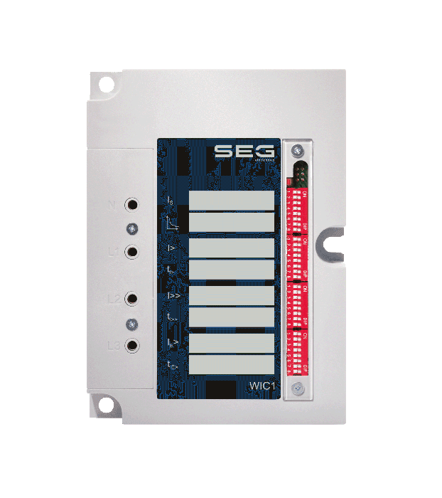
WIC1 CT Powered Time Overcurrent and Earth Current Relay (WIC11PE.)
Request an offer
Prices incl. VAT plus shipping costs Please configure your device with the selection fields available below. You must select a value for each field and then you can submit a price request.
Configuration
WIC1 – ANSI 50, 51
The WIC1 is a self/ct powered protection relay. No aux. voltage needed. Designed for harsh environment from -40°C up to +85°C. 20 years maintenance free.

Available Variants of the WIC1
WIC11PE | Self/CT powered Time Overcurrent and Earth Current protection relay, i. e. no aux. voltage needed. Designed for harsh environment from −40°C up to +85°C. 20 years maintenance-free. Settable via PC interface. |
WIC11PEW | Self/CT powered Time Overcurrent and Earth Current protection relay with backup protection element, i. e. no aux. voltage needed. Designed for harsh environment from −40°C up to +85°C. 20 years maintenance-free. Settable via PC interface. |
WIC12PE | Self/CT powered Time Overcurrent and Earth Current protection relay, i. e. no aux. voltage needed. Designed for harsh environment from −40°C up to +85°C. 20 years maintenance-free. Settable via DIP switches. |
WIC12PEW | Self/CT powered Time Overcurrent and Earth Current protection relay with backup protection element. No aux. voltage needed. Designed for harsh environment from −40°C up to +85°C. 20 years maintenance-free. Settable via DIP switches. |
WIC13PE | Self/CT powered Time Overcurrent and Earth Current protection relay, i. e. no aux. voltage needed. Designed for harsh environment from −40°C up to +85°C. 20 years maintenance-free. Settable via HEX switches. |
WIC14PE | Self/CT powered Time Overcurrent and Earth Current protection relay, i. e. no aux. voltage needed. Designed for harsh environment from −40°C up to +85°C. 20 years maintenance-free. With 2 PC interfaces, one at right angles to the other. Settable via PC interface, and the user can decide which one of the PC interfaces is positioned best related to his mounting needs. |
WIC1 Accessories: Current Transformers
Current Transformer (1 piece) (usable only for WIC1) | Order Code 1 | Order Code 2 (*) | ||
|---|---|---|---|---|
16 … 56 A | ⌀ = 50 mm | Class = 10P80 | WIC1W2AS1 | WIC1-CT2-10P (*) |
16 … 56 A | ⌀ = 50 mm | Class = 5P80 | WIC1WE2AS1 | WIC1-CT2-5P (*) |
32 … 112 A | ⌀ = 50 mm | Class = 5P80 | WIC1W3AS1 | WIC1-CT3 (*) |
64 … 224 A | ⌀ = 50 mm | Class = 5P80 | WIC1W4AS1 | WIC1-CT4 (*) |
128 … 448 A | ⌀ = 50 mm | Class = 5P80 | WIC1W5AS1 | WIC1-CT5 (*) |
256 … 896 A | ⌀ = 50 mm | Class = 5P80 | WIC1W6AS1 | — |
(*) Ask for availability.
General consideration how to select the right CT:
Calculate the nominal current: IN = SNtransformer / (UN ⋅ √3)
Look up the CT in the table above with the current range that fits best to this calculation.
If the table lists two matching CTs then it is advisable to prefer the one that allows for an optimal measurement of the short-circuit current to be expected. The short-circuit current can be measured up to the listed upper value multiplied by 20. For example: For the WIC1W2AS1, the short-circuit current can be measured up to 20⋅56 A = 1120 A. The system can withstand a primary current of 20 kA for 3 seconds, and 25 kA for 1 second.
WIC1 Accessory: Communication Adapter WIC1PC3
| Order Code |
|---|---|
PC adapter for a USB connection incl. software (usable only for WIC1) The adapter allows for making settings via PC (only WIC11 and WIC14), and for transmitting settings values and fault values from the WIC1 to the PC. | WIC1PC3 |
WIC1 Accessory: Watchdog Test Unit WIC1TU
| Order Code |
|---|---|
Watchdog Test Unit, for a function test of the CPU of a WIC1. | WIC1TU |
WIC1+WIB1+WIP1 Accessory: Flag Indicators
| Order Code |
|---|---|
Flag indicator, for a mechanical trip signaling independent of external (auxiliary) voltages. | WI1SZ4 |
Flag indicator, for a mechanical trip signaling independent of external (auxiliary) voltages, including a bistable signal contact 230 V AC, 3 A. | WI1SZ5 |
CT/Self-powered – No auxiliary supply voltage needed
Designed for harsh environment
Compact form factor
The WI Line devices are self-powered – The protection relay does not need supply voltages for Ring Main Units (RMUs).
The primary application of WI Line devices is Feeder Protection (also as backup) that does not need supply voltage.

